China World Technology Medical Equipment Service Group
Win-win together!
 |
| Brand Name: | Med-tronic |
| Model Number: | BMW001248 30SEP02 3201966-005H |
| Minimum Order Quantity: | 1pcs |
|---|---|
| Packaging Details: | Carton |
| Delivery Time: | 3-5 working days |
| Payment Terms: | Full Before Shipment | Product Name: | BMW001248 30SEP02 3201966-005H Med-tronic LP20e Defibrillator UI PCB Board |
|---|---|---|---|
| Brand: | Med-tronic | Part No: | BMW001248 30SEP02 3201966-005H |
| Warranty: | 90 Days | Applicated Machine: | Med-tronic LP20e |
| MOQ: | One Piece | Delivery Time: | 3-5 Working Days |
| Delivery Method: | DHL,UPS ,Fedex ,etc | Payment Method: | T/T ,Paypal ,Western Union |
| Package: | Carton | ||
| High Light: | Med-tronic LP20e Defibrillator Machine Parts,BMW001248 Defibrillator Machine Parts,30SEP02 Defibrillator PCB Board |
||
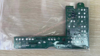
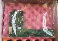
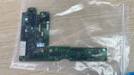
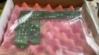
BMW001248 30SEP02 3201966-005H Med-tronic LP20e Defibrillator UI PCB Board
About UI PCB board
The User Interface (UI) PCB is responsible for displaying captured data to on-screen monitors and printers and receiving all user input. The main communication between the user interface PCB and the rest of the device is via the data bus. The RISC processor and digital memory form the CPU, which handles communication with the system's control PCB. The Pigtail User Interface provides the Philipilipysical connection between the User Interface PCB and the Patient Settings PCB.
The main user interface PCB subsystems are:
■ Power Supply: The UI PCB uses the keyboard SW_VBatt (change battery voltage) to generate four power supplies for the entire PCB as follows:
- +3.3 V logic supply to drive the A11 liquid crystal display (LCD) and the printer
- +3.3 V logic supply for CPU processor and memory
- +2.5 V logic supply for FPGA
| Item name | Med-tronic LP20e defibrillator UI board BMW001248 30SEP02 3201966-005H |
| Brand | Med-tronic |
| Model | BMW001248 30SEP02 3201966-005H |
| Use place | Hospital Devices; Medical Care; ICU; |
| Deliver time | 3-5 days |
| Warranty | 90 days |
NOTE: The following devices must be removed before you begin:
disassemble:
- trunk
- Front shell
-Active View Component
To remove PCB from the user interface:
1. Disconnect the W18 user interface flex cable from the user interface circuit board in J31.
2. Disconnect the speed dial connector from PCB UI J32.
3. Remove and remove the three 4-40 x 0.312 (173) screws from the bottom of the user interface PCB. Remove the two ground harnesses (221) attached to the left and right corner bolts.
NOTE: Replace damaged or worn ground wire harness.
NOTE: When you replace the User Interface PCB, you must ground the new PCB.
4. Unscrew and remove the 4-40 x 0.312 (173) screw in the upper left corner of the user interface PCB.
5. Remove the three nuts 4-40 (161) from the UI PCB. Remove the two ground wires attached to the center nut.
6. Remove the circuit board from the ring user interface.
![]()
![]()
![]()
To install the UI PCB board :
1. Place the UI PCB on the front of the chassis
2. Insert speed dial unit ground harness and second ground on lower center stud and install three 4-40 nuts on interface plate User ID ; torque nut 6.8 in-lbs. See Ground Harness Orientation to locate the ground harness.
3. Attach the two ground wires to the new studs at the bottom left and right 4-40 x .312 ; torque up to 6.8 in-lbs.
4. Install two new 4-40 x 0.312 screws for PCB UI ; torque up to 6.8 in-lbs. See Ground Harness Orientation to locate the ground harness.
Note: Replace a damaged or broken ground wire.
5. Connect the speed dial connector to circuit board J32 UI .
6. Connect the W18 UI Flex cable to the J31 UI PCB.
7. Complete the process by installing the active screen.
If you're interested in BMW001248 30SEP02 3201966-005H Med-tronic LP20e Defibrillator UI PCB Board ,feel free to contact us .Thank you .
Contact Person: Kiara
Tel: 8619854815217