China World Technology Medical Equipment Service Group
Win-win together!
 |
| Model Number: | Dash4000 |
| Minimum Order Quantity: | 1pcs |
|---|---|
| Packaging Details: | Carton |
| Delivery Time: | 3-5 working days |
| Payment Terms: | T/T(wire transfer), Western Union, Paypal |
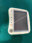
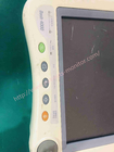
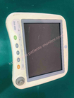
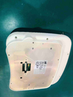
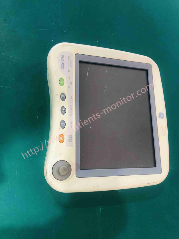
| Brand Name: | GE | Product Name: | 004-0004-004 2016792-002 REV A GE Dash4000 Patient Monitor Display Assembly |
|---|---|---|---|
| Part No: | 004-0004-004 2016792-002 | Condition: | Used |
| Size: | Dash 3000 – 8.4 In., Dash 4000 – 10.4 In., Dash 5000 – 12.1 In | Type: | Active-matrix Color LCD |
| Resolution: | Dash 3000 And 4000: 640 By 480 Dpi, Dash 5000: 800 By 600 Dpi | Number Of Traces: | 7 (maximum) |
| Number Of Seconds/trace: | 4.9 At 25 Mm/sec | Sweep Speed: | 6.25, 12.5, 25 Mm/sec (with Erase Bar) |
| High Light: | Dash4000 Patient Monitor Display,004-0004-004 Patient Monitor Display,2016792-002 Patient Monitor Display |
||
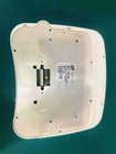
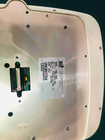
004-0004-004 2016792-002 REV A GE Dash4000 patient monitor display assembly 10.4inch
Display Specification
| Size | Dash 3000 – 8.4 in., Dash 4000 – 10.4 in., Dash 5000 – 12.1 in |
| Type | Active-matrix color LCD |
| Resolution | Dash 3000 and 4000: 640 by 480 dpi, Dash 5000: 800 by 600 dpi |
| Number of traces | 7 (maximum) |
| Number of seconds/trace | 4.9 at 25 mm/sec |
| Sweep speed | 6.25, 12.5, 25 mm/sec (with erase bar) |
![]()
Removing or replacing the display assembly
1. Remove the handle assembly from the patient monitor.
2. Place the patient monitor on a non-corrosive, non-static surface. Make sure the trim knob controls hang from the edge of the surface to avoid damage.
3. Use a pair of pliers screwdrivers to remove the four screws that secure the display unit to the main unit (six screws for the Dash 5000 patient display).
4. Separate the display assembly from the main unit and look inside the unit to determine how the display flex cable is folded. Depending on the model, the Dash patient monitor may have a monitor flex cable that folds up from the bottom or right side of the monitor.
The location of the folds determines how the display assembly is positioned for removal from the main unit.
Caution :Damaged cables - Do not kink, pinch, stretch, twist or tightly fold the display flex cable. If you don't handle bending the cable gently, you will damage the cable.
![]()
![]()
5. To prevent damage to the display flex cable, bend the display assembly to the patient monitor being serviced.
Display assembly with green display shield
![]()
Display assembly with gold display shield
![]()
6.Remove the two screws that connect the flex circuit to the main unit's CPU/battery housing assembly. Remove the flex connector by pulling on the elastic of the flex connector.
![]()
7.Remove the DAS connector by lifting the latch and the card
![]()
8. Place the display assembly face down on a non-static, non-abrasive surface. Make sure the trim knob controls hang over the edge of the surface to avoid damage.
9. Replace the defective monitor assembly.
10. To replace the display elastic component
11. To replace the main unit parts
12. Refer to the diagram below to determine if it is necessary to enable or disable the warning light on the instrument display assembly.
![]()
![]()
a. To enable the alarm lamp option, make sure the alarm lamp jumper is connected to the two J2 pins on the alarm lamp PCB.
b. To disable the alarm lamp option, remove the jumper from the alarm lamp PCB or connect the jumper to a single J2 pin on the alarm lamp PCB.
13. Connect the display unit to the main unit.
14. Reassemble the patient monitor in reverse order.
15. Attach the test leads faceplate labels as shown in the figure below.
![]()
![]()
Contact Person: Kiara
Tel: 8619854815217